Disclaimer: This posting is a work in progress. I’ve mode this some years ago and was asked to provide some documentation:
I have parts of a SAIA PCDII that I wanted to make use out of. The ourput boards have 6 relais each and 8 of them are connected to a backplane connector. This makes 48 mains voltage (low current) switchable channels.
Confusing what I mean? Have a look at this video
I’ve found some of the pictures I took while working on this and just a few days ago I found the box with the hardware itself.
For now the old pictures.
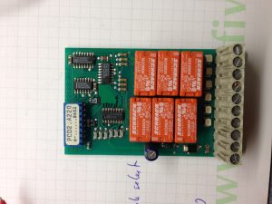
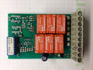
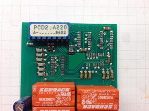
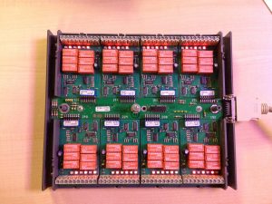
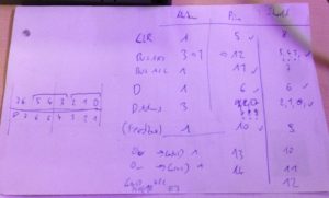
Unfortunately I just this one picture of the pin out.
Links
TODO:
- redraw schematic
- Figure out connector type
- sketch pinout of PCD2.A220 board
- sketch pinout backplane
- comment ino file
Hello, can you share Saia cable pin description? Its very important to me. Please…
I cant find “SayaPLSmanual.pdf” doc… can you share again?
Hi Kenan,
the link should be working now.
have fun
https://filehost.elektronaut.at/download/pdf/SayaPLSmanual.pdf
Hi thanks, there is nothing inside about that project. Its general documentation.
I can not read your handwriting :) Anyway its not important…
Arduino pins 0,1,2,3,4,5 are okay…
But its not clear arduino pins 6,7,8,9,10,11,12 … where to connect on cable or bus board?… Listen, reset, enable, feedback etc…
Please do me one last favor… It will change my life :D
Regards
Hi thanks, there is nothing inside about that project. Its general documentation.
I can not read your handwriting :) Anyway its not important…
Arduino pins 0,1,2,3,4,5 are okay…
But its not clear arduino pins 6,7,8,9,10,11,12 … where to connect on cable or bus board?… Listen, reset, enable, feedback etc…
Please do me one last favor… Or sell the cable and protoshield to me :D :D :D
It will change my life ;)
Regards